Once It arrived in the mail I was left with the dilemma of how to actually put it to use. The answer showed up in the form of a woodworking 101 project.
The entire project took about 4 hours of my time over two days and cost me a total of around 60-65 Dollars. It would be more or less depending on the meter since they are running 10 to 40 bucks and what bells and whistles you would want on your housing.
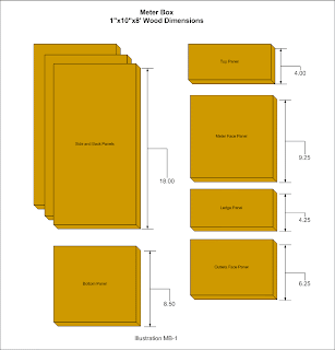
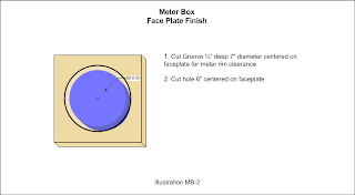
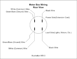
Here's some support info for the meter housing.


The list of wiring guides are at the General Electric Meter Wiring Guides in case you are using a different model of GE meter.
And the Parts List
- (1) Carry handle
- (1) used extension cord to be remade into the power cord (20 feet will do)
- (1) pound box of 2" deck screws
- (1) 1"x10"x8' pine board to cut down according to MB-1
- (1) 9" 2"x4" scrap board to cut down to 1"x1-1/2"x9"
- (4) 1/4"-20x1" bolts
- (4) 1/4"-20 nuts
- (8) 1/4" washers
- (2) 3/8"-16x2" Bolts
- (2) 3/8"-16 nuts
- (2) 3/8" washers
- (2) Coat Hooks with mounting screws
- (1) JB Weld or equivalent epoxy
- (2) 1-5/8" Screws
- (1) 3 gang electrical box, old work
- (1) 3 gang switch cover, large square type
- (1) rocker type light switch
- (2) outlets, square face type
- (1) 5 foot length 12/2 or 14/2 electrical wire.
- (1) GE Watt Hour Meter, IW-70-S model preferred, but I-70-S works too.
Publish Post
Gadgets & Gizmos Articles
Next: Receiving and Setting Up a Scan Gauge II
Previous:
Lab Projects Articles
Next:
Previous: Changes to the Test Pressure Chamber


1 comment:
Thanks for this article - I just purchased an I-70-S meter off of Ebay and this shows exactly how to wire it up, and the fact that you can run it at 120 volts.
-- Mike
Post a Comment