Monday, June 30, 2008

Test Enclosure Parts and Plans

The Rabbit Cage was a straight forward construction project, with the aim to produce a means of containing the flying debris should an explosion occur.

Parts List

  • (3) 2"x2"x8' white pine board
  • (1) 2"x3"x8' white pine board
  • (1) 1"x8"x8' white pine board
  • (1) pair small door hinges
  • (1) pair chest handles
  • (1) 3'x10' 15 gauge hardware cloth
  • (1) Door Latch
  • (1lb) 2" Wood Deck Screws
  • (3) packs 1/4"x1" metal roofing screws with rubber & steel washers
  • (1) 1/8"x30"x30" sheet of Plexiglas


Tools List

  • Saw, preferably electric
  • Screwdriver, preferably an electric drill driver
  • Tape Measure
  • Square, Unless saw has a guide
  • Pencil, Pen or Sharpie
  • Sheet metal cutters
  • nut driver, socket wrench 1/4", or socket adaptor for drill driver.
  • 3/16" Drill bit
  • Electric Drill or Hand Drill
  • Scratch Awl, nail, or other sharp pointed tool


I wanted the overall dimensions to be 26" Wide by 25" Deep by 27" inches high. The plans are drawn up accordingly.

1. Cut the wood frame and door frame parts from 2"x2" and 2"x3"

  • (4) 2"x2"x26"
  • (3) 2"x2"x20.5"
  • (4) 2"x2"x24"
  • (2) 2"x3"x20.5"
  • (2) 2"x2"x22"
  • (2) 2"x2"x17.5"


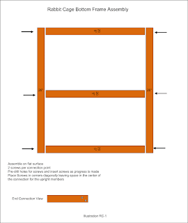
2. Assemble the bottom frame from two 26" and three 20.5" 2"x2". See Illustration RC-1.


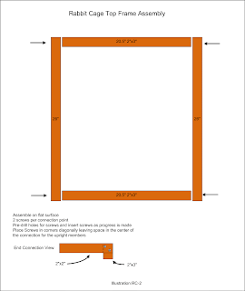
3. Assemble the top frame from two 26" 2"x2"s and the two 2"x3"s. See Illustration RC-2.


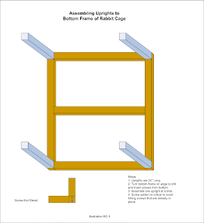
4. Take the assembled bottom frame and four 24" 2"x2"s and screw them together to form a bottom frame with side frames attached. See Illustration RC-3.


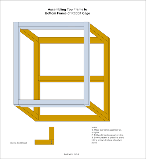
5. Take the bottom frame with attached sides and screw the top frame to it to complete the basic cage frame. See Illustration RC-4.


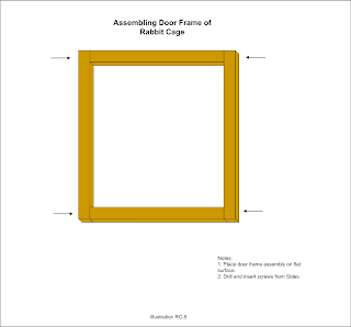
6. take the two 22" 2"x2"s and the two 17.5" 2"x2"s and screw them together to complete the basic door frame. See Illustration RC-5.


7. Cut hardware cloth to size to fit on the INSIDE of the door. Screw down starting in the corners then the center of each side of the door frame and thereafter advancing around the door frame until the hardware cloth is attached to the door frame by a screw every 4-5 inches. See Illustration RC-6.
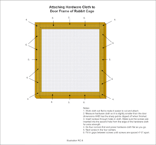


8. Cut hardware cloth to fit the right side cage frame opening and repeat the screw down procedures used in step 7. This time the hardware cloth fits on the outside of the cage. See Illustration RC-6.

9. Cut hardware cloth to fit the back cage frame opening and repeat the screw down procedures used in step 7. Again the hardware cloth fits on the outside of the cage. See Illustration RC-6.

10. Cut 2 pieces of hardware cloth to fit the top cage frame opening, place the two pieces together one on top of the other and repeat the screw down procedures used in step 7. Once again the hardware cloth fits on the outside of the cage. See Illustration RC-6.

11. Cut three 1"x8"x26" pieces of wood and notch two of them so all three will fit in the bottom of the cage as a floor. Screw down with 2 screws per board at each end.

12. Mount the hinges to the door by aligning the hinges to the left edge of the door and screw them down. Place a piece of cardboard on the bottom of the cage hanging out a little where the door will mount. This technique serves as a spacer. Screw down the hinges to the cage frame.

13. Mount the cage carry handles to the 2"x3" sections of the upper portion of the cage, first by measuring the length and marking the center, then screw them down.

14. Mount the door latch to the door by screwing it down, then mount the door latch catch to the cage frame by screwing it down.

15. Make sure the Plexiglas sheet is cut to fit the front opening of the cage. Carefully drill large enough holes in the Plexiglas sheet so the screws will pass through the sheet without the threads hanging up. Mount the Plexiglas sheet first by the top two corners then the bottom two corners, then finish by screwing down the rest of the screws.

16. Cleanup.

Lab Projects Articles


Next: Building a Hydrogen Exhaust Hood
Previous: Introducing the Rabbit Cage
Thursday, June 26, 2008

Introducing the Rabbit Cage

After the test accident I suspended testing until I built an enclosure to house the electrolyzer containers in case of a blow off and the result is the Rabbit Cage.


It still needs to have her "Baptism of Fire" to make sure it's sturdy enough to call safe. We'll see after the next round of carnage.

Lab Projects Articles


Next: Test Enclosure, Parts and Plans
Previous: Changes to the Test Control Panel - 24 June 08

Blooper of the Day!

Cut! Cut! Cut! This one's not in the can.

Smack's Booster Initial Test with Unexpected Results

I performed the first test of the Smack's Booster with a Simpleton plate assembly and had a horrific result.


Needless to say, over-amping the electrolyzer has quite a risk to it.

I neglected to mention that the booster was drawing just about 30 Amps when it blew. Additionally, I was looking right at the booster when it popped and the flame was orange. No mistake there.

I plan to test this some more, but not without an enclosure, which I plan on building forthwith.

Lastly, I wonder if the brown scum has something to do with it. Only testing will bear this out. I have an inkling that the scum is ferrous oxide which was liberated from the stainless steel parts. It sure looks like rust water to me at any rate.

Resistance Testing a Smack's Booster with Simpleton Plate Arrangement

I put together several clips as one regarding resistance testing the Simpleton plate arrangement and this is the result.


I determined that the resistance climbs rapidly before leveling off. I should test with a different multimeter to see if it is the result of using a digital one versus an analog one.

Second, it appears that very little NaOH is required, around a half a teaspoon should do it. More doesn't seem to affect the resistance.

Third, the resistance appears to drop 300-400 Ohms when using Sodium Hydroxide versus tap water. To give some indication, my water was tested about a year ago and it had 22 grains of hardness. Yes, I know, like a brick. I was told at the same time that during the summer, the hardness drops way off due to pumping in water from a nearby reservoir, but I have no way of testing that at this time.

Smack's Booster Simpleton Plate Assembly

I put together a short video clip of me assembling a Smack's Booster with what I call a Simpleton Plate Assembly. I intend to test this setup to get some baseline figures and learn more about the design in the process.

Tuesday, June 24, 2008

Common Electrolytes Examined

I picked up a grocery sack full of potential electrolytes to experiment with in hopes of finding a suitable electrolyte to use in my hydroxy gas experiments.

They are:


I forgot to mention that Sodium Hydroxide will also draw CO2 out of the air, plus Potassium Hydroxide is also highly caustic. This pair seem to hold the most promise as electrolytes, but are also the most hazardous to handle.

So there it is. I might find more, but this is the electrolyte lineup.

Electrolytes & Electrolyte Testing


Next:
Previous: Buying the Electrolyte

Product Review: Extech IR Thermometer

I found a nifty widget at Lowe's today in the Electrical department. It's called an Extech IR Thermometer. It reads the surface temperature of anything you point it at up to over 700 degrees Fahrenheit.


It was mine for 58 smackers and slugs. If only it cost half as much...

Gadgets & Gizmos Articles


Next:
Previous: What on Earth am I Doing?

Changes to the Test Control Panel, 24 June 08

Having never met something that I thought was good enough, I ripped into the just completed power panel to make some necessary "improvements".


I installed a double cigarette lighter assembly so I can press the Test Control Panel into a charger/power supply role.


I reworked this test panel to just include the Ammeter and added a 12 volt light for a test load.


I drilled a hole and inserted the 12 Volt light just below the Ammeter and Vacuum/Boost gauge.


Another view capturing all of the changes I made.

And now for the rest of the blah, blah blah.

Lab Projects Articles


Related: Demo of Auxiliary Power Input on the Test Control Panel
Next: Introducing the Rabbit Cage
Previous: Light Dimmer Switch as a 12 Volt Rheostat: Failure

Light Dimmer Switch as 12 Volt Reostat: Failure

I tried and tried, but just couldn't get the darn dimmer switch to work. Conclude for yourself in this video clip.


It just shows how much I have to learn about electronics. I can only assume that there's stuff in the switch that works at 120 volts AC, but won't work at 12 volts DC.

Lab Projects Articles


Next: Changes to the Test Control Panel - 24 June
Previous: Converting a Computer ATX Power Supply to a Lab Power Supply - Part 3
Related: Constructing a Test Control Panel

Sunday, June 22, 2008

Blow Off Testing a Smack's Booster Electrolyzer Container Lid

I wanted to check the safety of the Smack's Booster Electrolyzer Container when it is assembled with plumbers silicone grease as a gas seal inside the top of the container. I'm a bit worried that it may cause the top to seize instead of pop off.

So what I did was devise a test to inject compressed air into the container to see what it does.


Here are the test parts.

  • 4" PVC Cleanout Cap Square Head
  • Metal Tubeless Tire Valve


And here is the completed assembly. It also required a 7/16" drill bit in order to get the correct diameter hole for the valve.

After several tests with compressed air, I determined that it takes very little pressure for the top to pop loose, which relieved my concern that it may cause an explosion.


Of course I just had to record the event for posterity.

UPDATE: 30 July 2008

I had a person ask about this setup and it made me realize that the article could be taken out of context. The test was to determine if I could perform experiments using plumber's silicone grease to seal the top without leaking while allowing for a blow off should a backflash occur. The answer is; the plumber's silicone grease can provide a seal, but it seems to be very vulnerable to leakage which will affect productivity and test results. As for the possibility of a backflash, I've had that happen once already and it put a nice dent in the ceiling of my garage.

Saturday, June 21, 2008

Converting a Computer ATX Power Supply to a Lab Power Supply - Part 3

I finally finished the test control panel and installed the power supply in it so I went ahead and performed the final tests of the power supply. It seems a bit disruptive to have to weave the two projects together, but the result is well worth it..


Lab Projects Articles


Next: Light Dimmer Switch as a 12 Volt Rheostat: Failure
Previous: Constructing a Test Control Panel
Related: Converting an ATX Power Supply to a Lab Power Supply - Part 2

Friday, June 20, 2008

Constructing a Test Control Panel

After looking at the pile of test gadgets, I decided I had to do something to organize it into something useful. I hit on the idea of a test control panel, but what to make the darn thing out of? How about wood?! Easy enough to work, doesn't have to be pretty, and easy enough to modify as well(provided I have the tools I need to do so).

So off to the store to get yet more parts. I swear this experimenting thing just eats money like it's fillet Mignon.


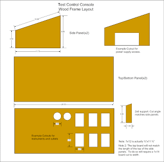
I started with a simple plan to build an open front/back box with an angled top for better ergonomics. This layout shows the dimensions I used to cut the wood.


Here's the basic frame parts after I cut them from a piece of 1x12x6 and a piece of 2x6 for extra support.


I started building the box from the bottom. I used deck screws 2" long in which case I had to drill pilot holes for each screw to avoid splitting the wood. You could use box nails instead, but it would be a little less sturdy when finished.


Here I'm screwing down the computer power supply which will provide the juice for the control panel. I had to drill 2 holes through the inside corners of the power supply case before screwing it down. There was a screw tab on the opposite side already which saved some hassle. The screws had to be less than 3/4" long to prevent coming out the bottom of the control panel.


That's done. Power Supply is in place.


OOPS! There's a lesson here. DO NOT DRILL HOLES OVER SOMETHING YOU DON"T WANT HOLES IN! The computer power supply experiment nearly came to an abrupt end.


Another view of my little gaff. Not much to see actually.


A stand back and experimental look at the work in progress.


Closeup of the Ammeter, Vacuum/Boost gauge, and Time/Temperature gauge.


Closeup of the meat thermometer.


Closeup of the two multimeters.


Closeup of the power switch.


Closeup of the Ammeter and Reostat jumpers.


Closeup of the dimmer switch as pressed into service as a reostat.


Closeup of the Igniter which was adapted from a gas grill replacement igniter kit.


Closeup of the first set of power jumpers from the ATX power supply.


Closeup of the second set of power jumpers from the ATX power supply.


Closeup view of the front of the control panel. I installed the rail to convert the space into a rat hole to store small items.


View of the left side. I added shed door handles to make it easier to move, not that it's heavy, just a little awkward without the handles.


A view of the back peeking into the rat hole.


And finaly a view of the right side with the port for the power supply.

The Finished Product


Lab Projects Articles


Related: Light Dimmer Switch as a 12 Volt Rheostat: Failure
Next: Converting a Computer ATX Power Supply to a Lab Power Supply, Part 3
Previous: Converting an ATX Power Supply to a Lab Power Supply, Part 2

Wednesday, June 18, 2008

Converting an ATX Power Supply to a Lab Power Supply, Part 2

Now for the fun part; ripping the power supply apart to begin the process of converting it to a Lab Power Supply.


First I chopped off the connectors to the peripherals using a pair of side cutters.


Then I inspected the motherboard connector and, there is indeed a green wire peeking out of the back.


I lopped off the connector with the side cutters as well.


I organized the wires by color.


I then soldered the green wire to the switch I bought along with a black wire.


I soldered the orange wires together and set that aside.


The "Load circuit" involves soldering a red wire to the 10 Ohm, 10 Watt resister and clamping it to the case as a heat sink. Note I put a rubber grommet around the wire bundle where it goes through the case. This is to prevent cutting through the wire insulation and causing a short.

At this point I had to stop because I couldn't mount the terminals to the power supply. Instead I'll begin construction of the Test Control Panel so I can finish the power supply assembly.

Lab Projects Articles


Related: Converting a Computer ATX Power Supply to a Lab Power Supply, Part 3
Next: Constructing a Test Control Panel
Previous: Making a Lab Power Supply from an ATX Computer Power Supply, Part 1

Making a Lab Power Supply from a Computer ATX Power Supply, Part 1

I found a video on YouTube.com that explains how to alter an ATX power supply for use as a Lab Power Supply. Sounded like an opportunity to use that old computer for something other than a dust magnet!

Search YouTube.com

Conversion Video

Anyway, I found the one that talks about how to perform the "surgery" using a How to convert an ATX Power Supply manual from WikiHow.com.

Part 1 - Removing the power supply


Here's the dust magnet! a Compaq that I used while I was working in Turkey. It has a 250 Watt power supply and it's about to have a heart deplant.


There's the power supply. No switch. Big deal. Yer mine anyway.
I'd hoped for a pic of the specs, but it washed out too bad. Oh well.


There's where the power supply connects to the motherboard, and look! Ferrite cores. Must make a note to remove them as well.


All these red/black/black/yellow connectors have to be disconnected as well.


Another angle of the connectors.


A closeup of the motherboard connector and the peripheral connectors all wadded up in my grubby mitt.


Now to loosen it up using a No. 1 Phillips screw driver and rip it out.


And there's the plunder, one 250 watt power supply, a fan, and a micro switch with two diodes still in the plastic mounting bracket. The ferrite donuts will come out later when I think of them.

Lab Projects Articles


Next: Converting an ATX Power Supply to a Lab Power Supply, Part 2
Previous: Setting Up the WorkBench

Monday, June 16, 2008

Test Electrolyzer Cap Construction

The first Electrolyzer cap is a test unit and I intend for it to have no bells or whistles to start out with, nor any fancy connections.


The obligatory group photo of the parts and some of the tools.

  • 3/8" ID clear vinyl tubing
  • (2) 1/4"-20x1-1/4" 3/16" Allen Stainless Steel Cap Screws
  • (2) 1/4" ID Neoprene Washers
  • (4) 1/4" SAE Stainless Steel Washers
  • (2) 1/4"-20 Jamb Knobs
  • (6) 1/4"-20 11mm Stainless Steel Nuts
  • (1) 4" PVC Cleanout Cap, Square Head


The first operation is to drill the holes for the electrode mounting bolts. The size was 1/4" to go with the 1/4"-20X1-1/4" 3/16" Allen cap screws.


The next operation is to drill the hole for the vinyl tubing. This should work fine with a 7/16" bit. The bit in the picture was 3/8". Careless of me not to measure the tubing to get the right bit size to begin with.


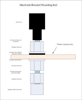
After assembly this is the finished product. The jamb nuts had to be ground a bit so they would turn in the tight space next to the square of the cap. Also, when assembling, make sure there are two threads of turn space between the first and second nut to allow for the insertion of the electrode bracket.


The underside view of the cap.


And finally the schematic of the bolt assembly.