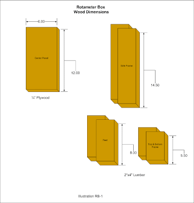
The first illustration shows the wood dimensions.

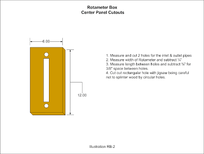
The second illustration shows the cuts to make in the center panel.

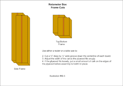
The third illustration shows the slots to cut in the frame pieces.

After cutting everything, the center panel and frame pieces are put together, lined up and fastened together using 2 inch deck screws, 2 per joint.
Next the feet are attached using 2 inch deck screws, 4 per foot.
The back light was a cheap outside light disassembled using a Dremel tool to cut away the riveted portion of the bracket, then the light fixture and bare bracket are attached to the wood frame using a 1 inch wood screw and washer. After that it's just a matter of wiring a lamp cord or extension cord wire to the light and nailing it down with wiring staples.
To see visually how everything goes together, just check out the video in Introducing the Rotameter
Gadgets & Gizmos Articles
Next: The Finished Rotameter Project
Previous: Introducing the Rotameter


No comments:
Post a Comment