Showing posts with label DIY. Show all posts

Monday, July 21, 2008

Building a Pressure Chamber to Test Oil Pressure Sensors

I got a crazy idea to test how oil pressure sensors actually work and this lab project is the result.


Parts List


  • (1) gas bottle, (never had gas is safe, used is cheaper)
  • (3) 1/2" black pipe tees
  • (3) 1/2" close fit black pipe (or the shortest pipe available)
  • (1) 3/4" to 1/2" Black Pipe Pipe Adapter
  • (4) 1/2" to 1/4" Black Pipe Adapter
  • (2) 1/4" brass male air connector
  • (2) 1/4" quarter turn air valves, male/female
  • (1) 1/4" air coupler, male
  • (1) 1/4" air coupler, female
  • (1) 1/4" Air Pressure Gauge
  • (1) 1/4" Air Coupler Quick Connect, female
  • (1) An oil pressure sensor that fits your vehicle


Personally I like to be able to drive my truck while I'm experimenting, otherwise I could just use the oil pressure sensor that's already on it.

The Ford oil pressure sensor I bought fits a 1/4" pipe adapter. Other makes and models may be different, so in that case you would have to adjust the parts list to get the sensor to fit. In the case of a metric sensor, fitment may be difficult without making your own adapter using a black pipe cap that you cut a hole in and tap to fit.

Lab Projects Articles


Next: Changes to the Test Pressure Chamber
Previous: Demo of Auxiliary Power Input on the Test Control Panel

Tuesday, July 15, 2008

Cleaning Stainless Steel Plate Assemblies with CLR

An HHO co-conspirator gave me a pretty cool tip on cleaning my stainless steel plate assemblies with CLR. So I decided to give it whirl.


Bottom line is: It works!

Basic Electronic Soldering Kit

I spend a moment talking about what you would need for a basic electronic soldering kit.


The basic list is:

  • Electronic Soldering Station(Elenco is fine for a beginner)
  • distilled water(for the sponge)
  • Heat Sink
  • scraper and brush set
  • Third hand magnifying and clamp set
  • rosin core solder
  • rosin

Monday, July 14, 2008

Plate Configuration Nomenclature 101

I've seen people around the Internet referring to their plate configurations using a particular method that seems to make sense.

So for those of you that aren't knowledgeable on this yet I'll attempt to explain it.

UPDATED: 29 July, 2008
UPDATED AGAIN: 9 August, 2008

General Concepts


For this section all plates, pipes, strips, rods, springs or any other shape that is used to electrolyze water is an electrode.

An electrode that is connected directly to the positive lead is designated with a plus sign (+).


An electrode that is connected directly to the negative lead is designated with a minus sign (-).


Electrodes that are not connected to either positive or negative leads, but are placed between them are both positive on one side and negative on the other. This is due to current jumping from the positive electrode to the negative surface of the unconnected electrode, then flowing through the electrode to the other side where it jumps off what is now the positive side of the electrode to the negative side of the adjoining electrode. These electrodes are referred to as neutral plates and are designated with the letter n.


Whenever three or more neutral electrodes are together in a design, the number of 'n's can be replaced by the actual number of adjacent neutral electrodes followed by an n. For example, there is a 31 plate design floating around the Internet and to use this example it would have 29 neutral electrodes in its configuration. This particular design would be written as such: +29n-.

For assemblies that use isolated cells use square braces [] to designate series configuration and parentheses {} to indicate parallel configuration.


Plate Assemblies


Plate assemblies can be flat, conical or bowled in shape, but generally flat and made from sheet metal. Plate assemblies are the dominant form of electrode so a designation normally is omitted. However, if needed the letter P may be used to designate plates like so: +P- If a plate assembly is conical, then the C modifier would be used like so: +CP- Likewise if a plate assembly is bowled, then the B modifier is used like so: +BP-

A really simple plate assembly with just one positive plate and one negative plate would have the nomenclature +-.


A slightly more complicated plate assembly with a neutral plate in the middle would be designated +n-.


A third example, where 6 plates alternate between positive and negative would have the following nomenclature: +-+-+-.


A fourth design with the negative plate in the center and positive plates on either end would look like this: +nnn-nnn+. The only difference from one variation to another would be the number of neutral plates.


The Smack's Booster design employs neutral plates that are connected electrically. To account for electrically connected neutral plates, use the / character between n's. It would look like this: +3n/n-3n/n+ to designate three pairs of connected neutral plates on either side of the negative plate. To improve readability the same design may include parentheses like so: +3(n/n)-3(n/n)+


A multi-cell design with 6 cells wired in series may look like so:
[+nn-][+nn-][+nn-][+nn-][+nn-][+nn-]. The same design my be abbreviated thus: 6[+nn-]


A multi-cell design with 4 cells wired in parallel may look like this:
{+nn-}{+nn-}{+nn-}{+nn-} or like this: 4{+nn-}


Pipe and Rod Assemblies


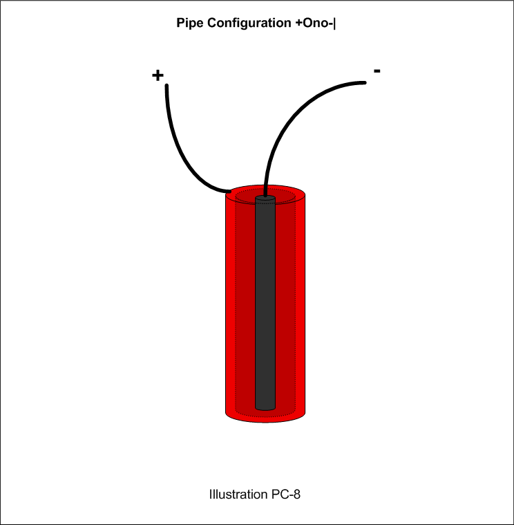
For pipe and rod type configurations, use the Capitol O for a outer pipe, the Small o for an inner pipe and the pipe character | for a rod. To write this nomenclature, first enter the polarity then the characteristic letter and repeat until finished. So a Pipe/Pipe/Rod configuration might be written +O-o+|.


To designate multiples, simply enter the number in the configuration and put the configuration in square braces or parentheses to indicate the connection type, like so 4[+O-o+|] to indicate 4 assemblies wired in series or 4{+O-o+|} to indicate the same but in parallel. If the four assemblies are in the same cell, then it would be written this way: [4(+O-o+|)] although they are more likely in parallel: {4(+O-o+|)}

Another possibility with the Pipe/Pipe/Rod configuration is that of the small pipe being neutral. It might look like so: +Ono-|.


Helical and Spring Designs


Additionally, for the one helical and one spring design I've seen, I suggest using the Ampersand (&) to indicate such. This example would be +&- to indicate the two plates actually wrap around each other.


For a spring design, the main difference would be that it is designated as a rod like so: +|&-|


Spiral Designs


A spiral assembly is one where the plates wrap one around the other to make a sort of compact spring. This type would be designated with the @ symbol like this: +@-.


Conclusion


From this a large variety of electrode combinations and designs can be represented; thus anyone should to be able to replicate a design from the plate configuration nomenclature and the plate dimension specifications. If I've missed something, please let me know.

Glossary


Polarity Designations
+ : Positive Electrode
- : Negative Electrode
n : Neutral Electrode

Wiring Designations
/ : Electrically Connected Plates(usually with a metallic nut, washers or spacers)
[] : Series wiring Configuration
{} : Parallel wiring Configuration

Shape Designations
P : Plate, optional
B : Bowled modifier for plate
C : Conical modifier for plate
O : Outer Pipe
o : Inner Pipe
| : Rod
& : Spring or Helix depending on rod or plate electrode
@ : Spiral plates

Multiplier and Grouping Designations
1-99 : The number of times to repeat the following designation.
() : Designation grouping. Used for improved readability.
[] : Series wiring Configuration (Indicates everything inside the braces are in a single cell)
{} : Parallel wiring Configuration (indicates everything inside the parentheses are inside a single cell)

Documentation & Terminology Articles


Next: Proposed Electrolysis Supplementation System Block Diagram
Previous: What on Earth am I Doing?

Saturday, July 12, 2008

Building a Hydrogen Exhaust Hood

I spent the better part of two days building a hydrogen exhaust hood and while the result is worth the effort I'm getting a bit tired of my old camera cutting off on me.


The entire project cost me about 40 Dollars and it is the very essence of "cheap but effective". If you have need of something similar, I hope this serves as an inspiration for ya.

Lab Projects Articles


Next: Demo of Auxiliary Power Input on the Test Control Panel
Previous: Test Enclosure Parts and Plans

Saturday, July 5, 2008

More Brown Scum Testing and Observations

I spent a few more hours testing and observing the formation of brown scum.


My Observations

1. The scum component and brown component are definitely separate.

2. The scum forms first.

3. The location of the scum on the surface is the result of hydrologic processes and not plate polarity.

4. The scum gathering on the surface is the result of bubble formation adhering to the scum at the surface.

5. The scum may form a film preventing or delaying bubble bursting but is barely detectable with a spoon insertion test.

6. The scum is heavier than water as it sinks when disturbed.

7. Plastic and adhesives have not been ruled out as a source of the scum, but is low on the list of possible sources.

8. Distilled water was not used, so water contaminants are also not ruled out as a source of the scum.


Additional theories

1. The scum may be minerals in the water which are percolating out of the water.

2. The scum is a separate compound from the brown color.

Safety Tips

I posted this in the HHOInfo forums and feel it's good to repeat here. I may update the post from time to time so it might be good to review it occasionally.

1. I use vinegar in a 1 quart spray bottle to neutralize NaOH or KOH if I suspect I've come in contact with it, then rinse off with fresh water. Keep the vinegar spray bottle within arm's reach of the test location.

2. Eye Goggles and rubber gloves are necessary when working with NaOH or KOH at all times.

3. I wear a good quality rain coat obtained at the local thrift store when running closed tests with NaOH or KOH. For open container tests it isn't so important.

4. I built a test enclosure to perform closed tests in as I've already had the top blow off a Smack's Booster trying to run it on the start(75 Amp) setting of my battery charger. Made a nice dent in the 10 foot ceiling of my garage and might have reached 40-50 feet altitude if outside. I believe the ignition cause was heat in the lead wires, but have not eliminated spark as a possibility.

5. Do not use glass for enclosed tests. Just too unsafe.

6. SS Wire leads in the electrolyzer container should be bulky whenever possible to reduce heat in the leads. If a wire isn't thick enough then wrap multiples together by twisting with vice-grips to produce a larger wire. SS Plate steel straps should be considered in place of SS wire leads due to the greater total cross section of the strap over wire(and thus less heat). SS straps can be made from cooking utensil handles in a pinch like Smack suggests on his website. If you don't like the cost, then get the utensils at the local thrift store, Dollar Tree, or garage sale. If there is a local scrap yard, inquire about purchasing what you need from them - at scrap prices.

7. Any Ammeter reading above 25 Amps during testing is flat dangerous in my opinion as the one blow off I've experienced was measuring 30 Amps at the time. If this sort of experiment is conducted, then make absolutely certain you have properly calculated and provided the required lead size in your container. I still haven't eliminated the possibility of arcing between the leads as the electrolyzer container is essentially a capacitor and over-energizing a capacitor will cause an arc.

8. Do not inhale the gas as you just don't know what is in there besides the HHO and some of the possibilities can mean an immediate and very long dirt nap.

9. If testing inside make sure to vent the gases to the outside as the Hydrogen will build up on the ceiling and ANY electrical spark will ignite it.

10. When using NaOH be sure you have a good quality source, such as Roebic Heavy Duty Drain Cleaner or Technical Grade NaOH with stated purity over 99%.

11. NaOH concentration should be low, 1/4 teaspoon per gallon of water is usually plenty. A high Ammeter reading(greater than 15) in low temps(less than 125F) indicates too much NaOH which should be replaced or diluted with fresh water. The exception to this rule may be when testing a large number of plates, which I haven't progressed to yet.

12. If using city tap water, place it in a container to sit uncapped for at least 24 hours before using to allow any Chlorine gas to vent out. Granted the potential amount is small, but the less Chlorine you are dealing with the better.

Thursday, July 3, 2008

Plate Conditioning Brown Scum Observations

I perform a 34 minute test to further condition the simpleton plate assembly and provide observations as I go.


What I learned.

1. The "scum" forms within 2-4 minutes.

2. The "brown" begins forming shortly afterward and slowly builds concentration throughout the test.

3. The "scum" doesn't seem to progress in volume along with the test.

4. The "scum" leaves a film on a spoon that is inserted into it while the "brown" does not seem to stay on the spoon with the "scum".

5. The "scum" isn't impermeable as larger bubbles trapped in the scum will pop. Tiny bubbles do not seem to pop as readily leading me to think the scum surface tension is higher than just the electrolyte.

6. The scum with trapped bubbles behaves like thick wet soap bubbles. To watch it during electrolysis, it behaves nearly like oil on water when it's disturbed by the fluid motion caused by electrolysis. So it has its own composition which is unlike the water/NaOH mixture.

7. After stoppng electrolysis, the "scum" dissapates rapidly, almost as fast as the trapped bubbles do.

8. The "brown" goes into a kind of suspension and hovers near the surface but not necessarily on the surface.

9. Disturbing the "brown" causes it to slowly sink.

My Theories

1. The "scum" and the "brown" are seperate compounds.

2. The scum seems to be a byproduct of the electrolysis, but to a limited extent.

3. The brown evidently is rust, but requires chemical analysis.

4. The scum may or may not be a distinct compound resulting from the electrolysis. It does seem to dissipate shortly after electrolysis stops.

Wednesday, July 2, 2008

Results of Running Plate Conditioning at the 75 Amp Setting

I discover what happens when I attempt to condition plates at the 75 Amp Setting of the battery charger. Yet another disaster diverted.